DDR
Comprehensive DDR Test Suite 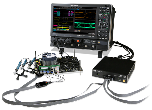
Teledyne LeCroy offers a full line of DDR test solutions for system bring-up, debug, performance analysis, and compliance. Teledyne LeCroy’s DDR test solutions ensure the right solution for every stage of development.
Physical Layer DDR Toolkit
The DDR Debug Toolkit provides test, debug, and analysis tools for the entire DDR design cycle. Unique DDR analysis capabilities provide automatic Read and Write burst separation, bursted data jitter analysis, and DDR-specific measurement parameters. All this DDR analysis can be performed simultaneously over four different measurement views.
Effortless Burst Separation
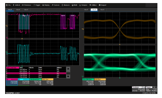
Automatic separation of Read and Write bursts eliminates the time-consuming process of manual burst identification and simplifies the analysis of DDR systems. Bursts can be separated based on DQ-DQS skew or based on the command bus when used in conjunction with the HDA125. The HDA125 additionally enables a unique "bus view", tabulating the Command Bus activity and placing color-coded overlays and annotations on top of the physical layer waveform in an intuitive manner.
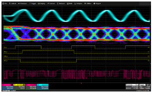
Eye Diagram Analysis
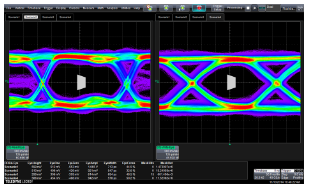
Any DQ, DQS or command/address signal can be tested against a standard or a custom defined mask, with up to 10 eye diagrams viewed simultaneously. Enabling mask failure indicators will automatically identify and locate the specific UI where any mask violation occurred. Built-in measurements such as eye height, eye width, and eye opening are critical to gaining a quantitative understanding of the system performance. With simultaneous eye measurements it is easy to compare performance across multiple testing views.
DDR-Specific Parameters
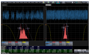
With a toolbox of parameters specific to DDR it is simple to quickly configure insightful measurements for validation, characterization, and debug. Up to 12 configurable measurements can be displayed and analyzed simultaneously across all active measurement views. For each measurement, advanced statistics such as min, max, mean, and number of measurement instances can be displayed and easily located with the searchable zoom feature.
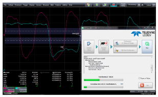
Physical Layer Compliance
The QualiPHY DDR packages perform all of the clock, electrical and timing tests per the JEDEC standards. Upon completion of each test run a report is generated which contains pass/fail results as well as fully annotated screenshots of the worst case measurement
Complete JEDEC Test Coverage
QualiPHY DDR packages preform all clock, electrical, and timing tests to conform the JEDEC specification. Additionally, eye diagrams are created to assist in debugging and to provide a high-level system overview. A limit set is included for each standard speed grade and can be fully customized.
Fully Annotated Screenshots

In addition to the measured value and the pass/fail status for each test, QualiPHY reports contain screenshots of the worst case measurement for each test. Each screenshot is fully annotated including trace labels and pertinent voltage levels.
Automatic Report Generation

Upon completion of each test run the QualiPHY software generates a compliance reports contain pass/fail results, all of the tested values, the specific test limits and fully annotated screenshots of the worst case measurement. Compliance Reports can be created as HTML, PDF or XML.
High-speed Digital Analyzer
The HDA125 turns your Teledyne LeCroy oscilloscope into the highest-performance, most flexible mixed-signal solution for DDR debug and evaluation. With 12.5 GS/s digital sampling rate on 18 input channels and the revolutionary QuickLink probing solution, validation of DDR interfaces has never been simpler or more comprehensive.
Command Bus Capture for Full Interface Visibility

Basic debugging and validation of embedded DDR interfaces typically involves analysis of the analog properties of the clock, data (DQ) and strobe (DQS) signals but when validation tasks become more complex and problems require deeper insight, the ability to trigger on, acquire and visualize the state of the DDR command bus is invaluable. The HDA125 brings command bus acquisition to Teledyne LeCroy’s already comprehensive toolset, providing the ultimate in memory bus analysis capability.
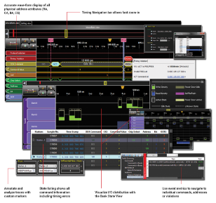
Analyze Bus Activity
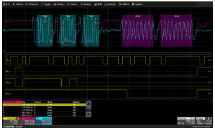
The HDA125 enables the unique “bus view” feature of the DDR Debug software option, which brings Teledyne LeCroy’s advanced bus analysis feature set to bear on DDR analysis. View bus activity in tabular form, and move time-correlated views to a desired event with the touch of a button. Search for specific events and bus states within the acquired record. Intuitive color overlays and annotations make it easy to identify areas of interest in the acquired analog waveforms.
Trigger on DDR Commands
The ability to trigger on specific states of the command bus becomes an invaluable tool for quick understanding of DDR signal quality. The HDA125’s logic triggering combines with the DDR Debug toolkit's intuitive setup and intelligent software cross-triggering to provide the ultimate DDR triggering system. Persistence maps of read and write bursts provide an easy and fast means of identifying subtle signal-quality problems for further investigation.
Protocol Compliance and Debug
A combination of quick and easy hardware setup and immediate feedback on violations allows users to quickly validate JEDEC timing compliance or swiftly identify problem areas with their memory system. Capturing the Command Address and Control bus, the Kibra 480 can quickly identify timing issues associated with the JEDEC defined speed bins.
Proprietary Probe Design
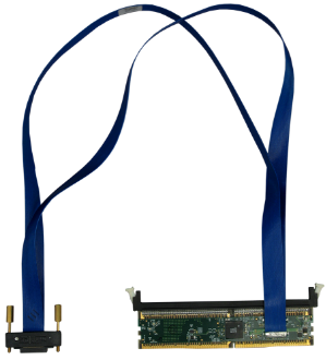
Teledyne LeCroy developed a custom ASIC for the Kibra 480 probe to support higher speed DDR modules. This proprietary probe implementation allows loss-less capture of DDR3 to 2133 MT/s; and DDR4 to 2400 MT/s and higher. The probes are self-powered to provide instant signal lock – including reliable capture of the DDR4 power-on sequence. Separate probes are available for DDR3 and DDR4 supporting UDIMM/RDIMM/LRDIMM and SODIMM as well as the newer hybrid NVDIMMs.
Easy Setup - No Calibration Needed

Start using the Kibra 480 immediately without time consuming calibration. Simply enter the memory controller parameters and start recording. The software will automatically load JEDEC trigger values for the DIMM type specified. Users can selectively disable or override any of the JEDEC triggers on-the-fly.
Traffic Summaries for Faster Analysis
In addition to timing analysis, the Kibra 480 generates performance metrics that are displayed for read, write and power down operations. Bus metrics are tracked per bank, per rank, and per channel to provide insights into overall memory utilization. The error report shows protocol and timing violations with hyperlinks to the error in question.